


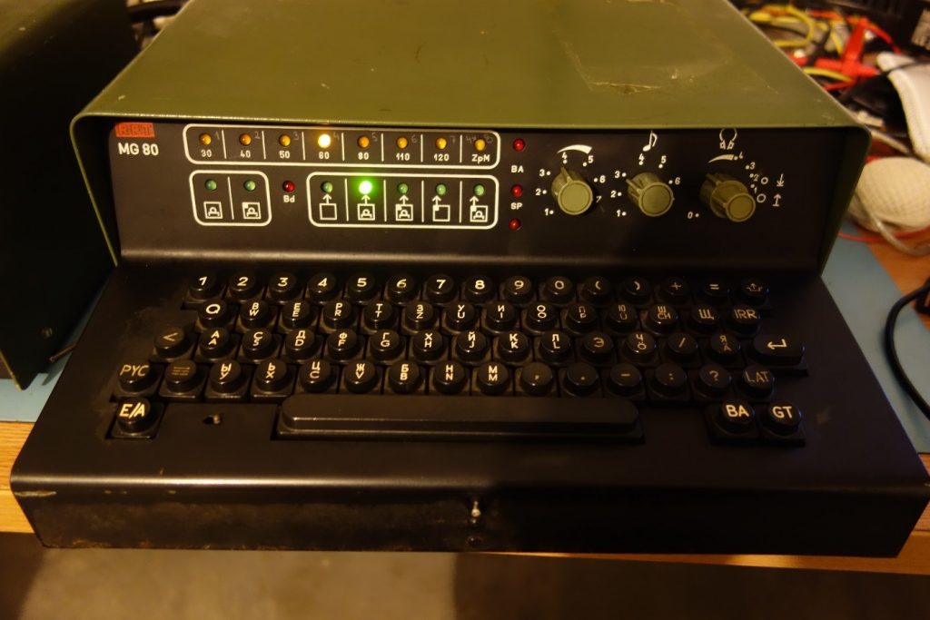
Few years ago, I happened to come across a strange machine, which looked like an electronic Teletype, but there was no punch tape mechanism or anything similar to it. A thought it must have been an externally attached device. After some research on the Internet, I found an answer to it. It is a device called burst encoder made in the GDR. There was a similar device in service in the Hungarian Army called R-014. However it only works in Teletype mode and could only send numbers. Luckily, there is lots of information about both devices on a Dutch webpage. Even the operating instructions may be found.
As I found out what it was, I was curious to see it working. According to the manual, it has a separate power supply, which I did not posses, but I recently found one on eBay. It was not too expensive, so I bought it quickly. Unfortunately, it did not include a cable. I continued searching for a pair of connectors, but anything I found was too expensive for my budget. So the question was: what can I do with that 32 pin monster, wondering what could be the pin configuration.
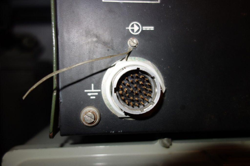
Months passed and I just could not find any connector for a reasonable price, not to mention a complete cable assembly. At some point I decided, I am not such a keen collector that I would need to keep everything perfectly to its original design, so I considered replacing that connector with something I might have laying around in my shack drawer? Alternatively, should I solder the cable in directly? However, the question of what each pin needs to be connected to is yet to be answered. Then I thought I might drop an email to the author of the webpage and ask for help. The answer came quickly and that made my day: it is a straight cable. This gave a push to the project. Therefore, I started sending emails to my collector friends. Maybe I am lucky and someone has something like this. Soon I got a male connector with a female socket from my friend Aron. It partially solved the problem, one remaining thing to solve. After a closer look to the socket, I realized that the German engineers were either smart or lazy, but the socket has the same internals as the plug. The pins and the insulator are identical; the difference is only in the holder. Therefore, I decided to cut the socket holder off that I consider barbaric, however sometimes we must take sacrifices. J It is almost a perfect fit, it just lacks the guiding and the locking, but with a little caution, I can live with it. If I ever find a matching plug, I may replace it in the future.
Then I learned and started to appreciate the work and effort of the workers who spent long days, months and years assembling these cables in the secret hidden factories during the cold war. The soldering and assembling of these connectors are such a labor intense job. It is even hard to imagine. I took me quite some time to finish both ends of the cable, not to mention that there is no room for error. I did not want the “magic smoke” to escape from the machine.
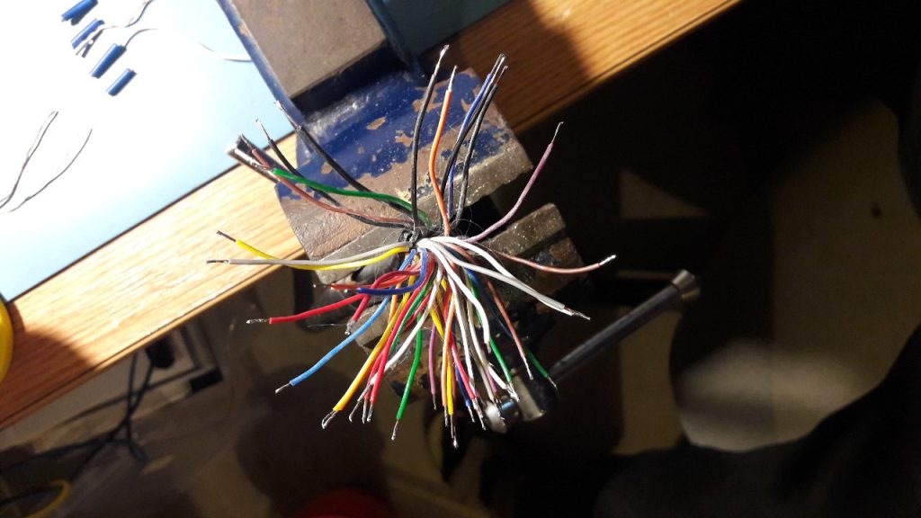
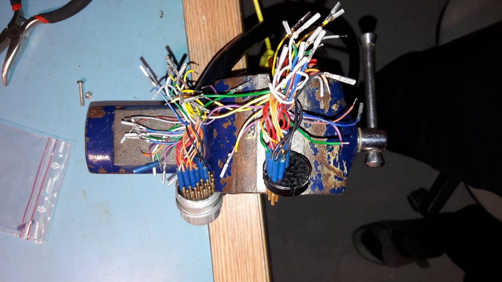
The „cable rose”
The connector was not a new stock, so I had to start removing the cut wire ends from each pin. They were not only soldered, but each pin had a folded/crimped part to it. It had to be done for 64 pieces and then I could start soldering in the new wires. I am not sure how long did this tedious endeavor take to complete, but it definitely took a very long time.
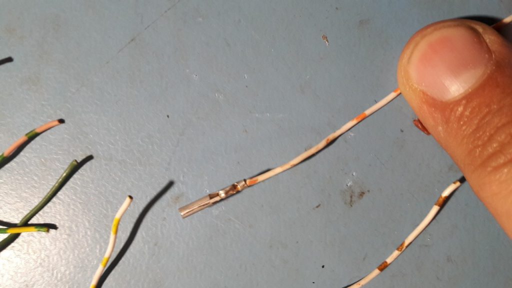
These are well-made joints.
After the first half completed, I felt relieved, but unfortunately, it did not last long. It was not done yet. I had to pay even more attention to the second half. The pins were too close together; I wanted to make it correct right at the first try. It would have been a disaster to fix a swopped connection at any later stage. I did not have a 32-wire cable, each wire identified by a unique color code, which could have made my job easier. I only had a cable with 8 different colors, so each wire had to be measured before completion, by using the same cable multiple times.
I am wondering what the original German assembly instruction
was . I am sure they had a better way to perform this tedious repetitive job without errors.
Finally, the job was complete. It looked well, measures good pin-to-pin. I was eagerly proceeding to the test. I plugged the cable into the mains and suddenly the LEDs came on.
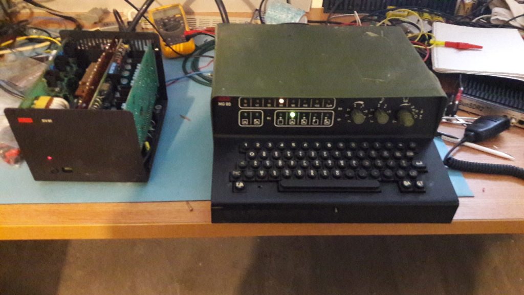
It did not only blink, but fortunately, the “magic smoke” did not leave the machine either.
The operation manual has a section of back connectors and pin-outs for the headphone. This was such a simple task to do after that monster 32-pin connector. I quickly soldered the wires for the speaker, and anticipated to hear the magic sound, but there was nothing. Unfortunately, I could not get more than some scratches and hiss out of the machine. There is not much left to do. It is time to crack the thing open and have a look!
Inside the usual DDR smell and look. The components are typical for the era, no surprises. Most importantly there was no, sign of burn or cannibalism.
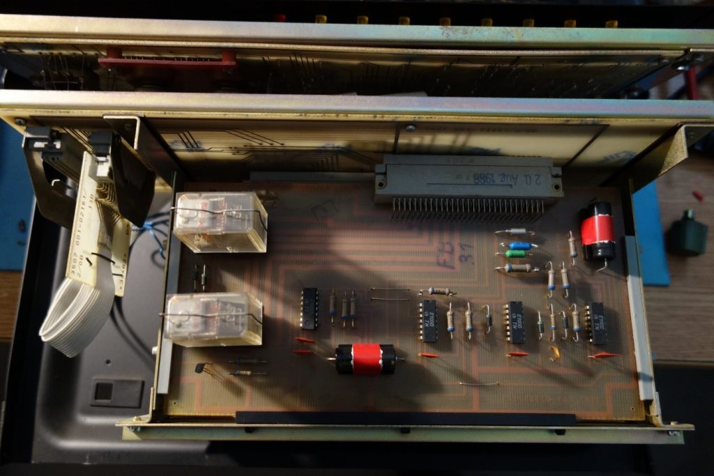
The top panel

The middle panel
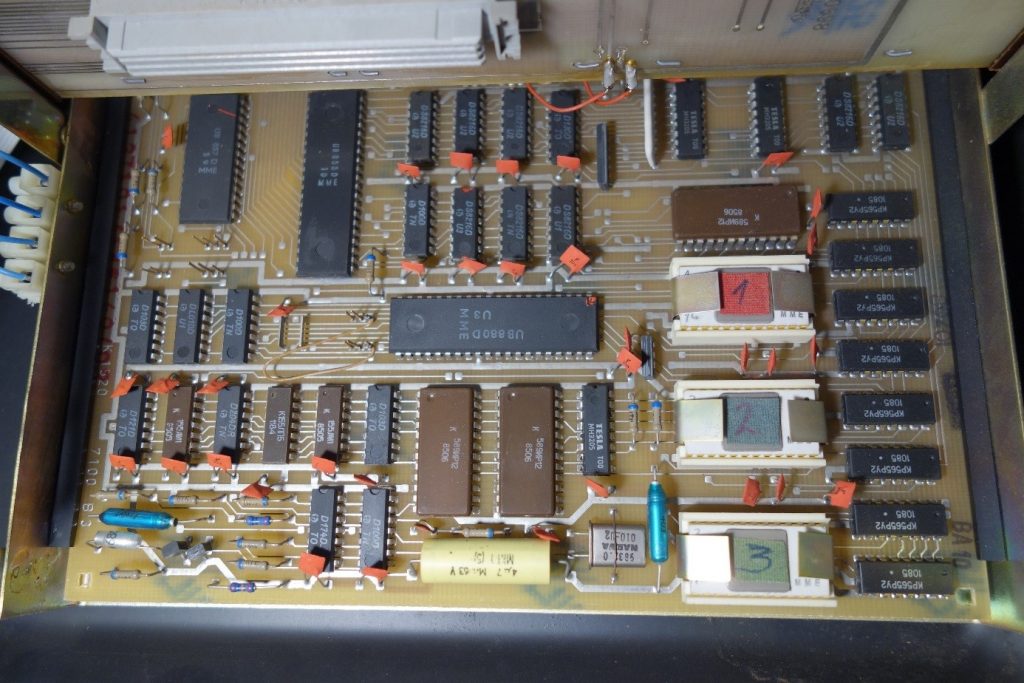
Recycling guys would kill for those golden pins of the ceramic base EPROMs.
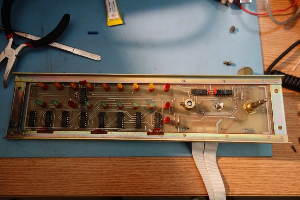
The „user interface” aka front panel.
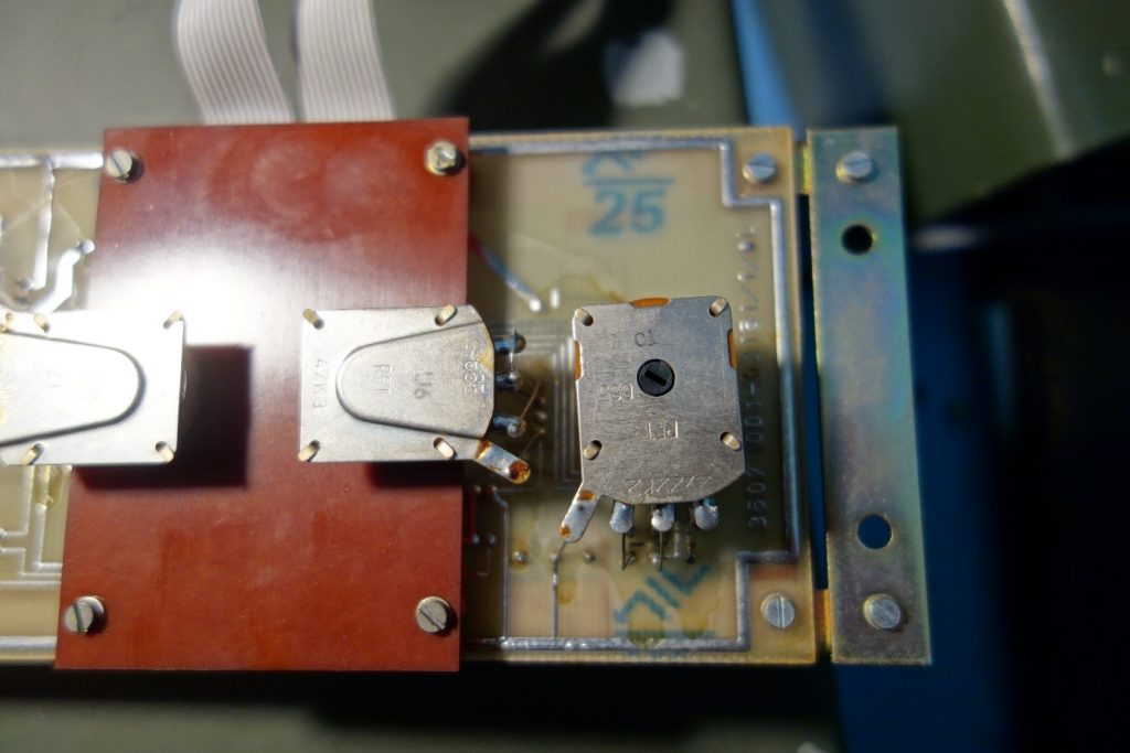
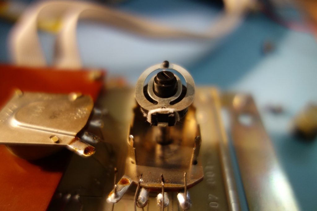
The „suspect”, volume control pot on the right.
This is a dual potentiometer. As usual, I happened NOT to have such a shape, value, and size among the countless salvaged parts in my bottom drawer. I had to think of another solution. So, what if I open up those four small pins holding it together and have a look? What could possible go wrong?
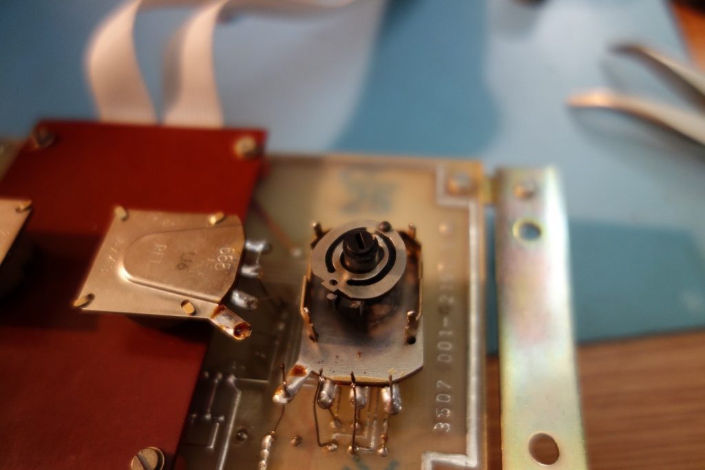
A sharp eye can immediately spot the problem
Of course, as I straightened the last pin, the whole thing fall apart and all the pieces flew off my desk. Luckily, I was able to collect all these pieces. Then, I matched and puzzled the whole thing back again; I quickly realized what had happened. The plastic pins holding the slide broke off and did not hold it in place anymore, therefore it never made contact to the resistor film.
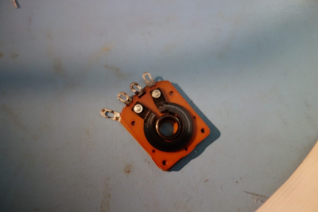
The carbon resistor film side of the potentiometer
I realized how brave I was to mess with such a delicate mechanism. The next question was: how creative I will be now? How would a professional restorer cope with such a challenge? Probably I will never find out, but let’s pick some wool thread and quick glue. J
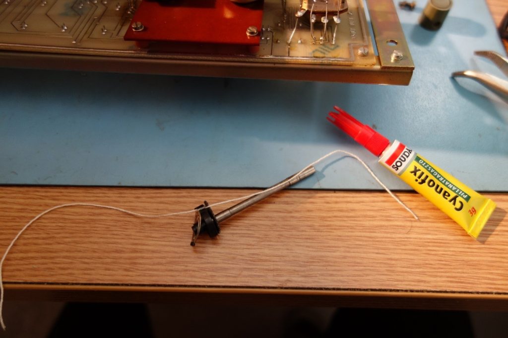
If this works…
t is not pretty, but this is what I learned from Mc Guiver
With hindsight, it was a piece of cake to put the thing together and give it another chance to shine in its original beauty. I am not sure how long it is going to last. It works! Finally, it came alive and has all the clicks and beep sounds as expected. It is always nice to see an old piece of hardware working again. I am not sure when was this used last time, but I am quite certain it was not in the near past.
Finally, I would like to thank my fellow collector friends who kept pushing me and inspired me to make this project happen. Special thanks for Aron for the connectors and to Paul for the pin-out diagram.
I hope this article will inspire the readers to dig out rare old equipment, and share with us their experiences and enrich our history of communications technology.
HA5TBN Daniel
At first it looked to me like a standard Cannon plug, maybe even one in aviation use, but that would have been too easy and also from the wrong side of the technology world. Congratulations on patience and persistence!
73