


by Istvan Agg, HA5CLF / N9EU
Not long ago I got bit by the retro feeling of building a regenerative receiver with electronic tubes, also called “Audion” receiver. What is the Audion or regenerative receiver? This excerpt is quoted from the Wikipedia (https://en.wikipedia.org/wiki/Audion_receiver)…
“An audion receiver makes use of a single vacuum tube or transistor to detect and amplify signals. […] The audion was invented by Lee De Forest.
In 1915 Edwin Armstrong developed an improved “regenerative” form of audion receiver that used the same vacuum tube for RF amplification, RF detection, and audio amplification.”
Recently I happened to glance over a simple schematic in an old book (Magyari Béla, “Rádió-Technikai Zsebkönyv”, ISBN 963 10 0672 7, 1975, page 883) depicting such a receiver. I have not built anything with electronic tubes since the 70’s. So, I decided to embark on satisfying my retro feeling constructing a vacuum tube circuit. I really wanted to build a transmitter, but what do I do with it without a receiver. So, I thought, let me build a receiver first.
Little did I know. What seems simple with tubes is much more complicated in real life. First, I had to order all sorts of components. I realized that if I were to build it with semiconductors, it would cost me a fraction of the cost than with tubes, besides the fact that I probably have all the components laying around in my drawers. Anyway, when you are bit with passion for glowing tubes in the evening dusk, cost does not matter.
I am not going to provide all the details, since I am not suggesting you build one of these, but I would like to tell you about my experience. It may be useful in your other projects.
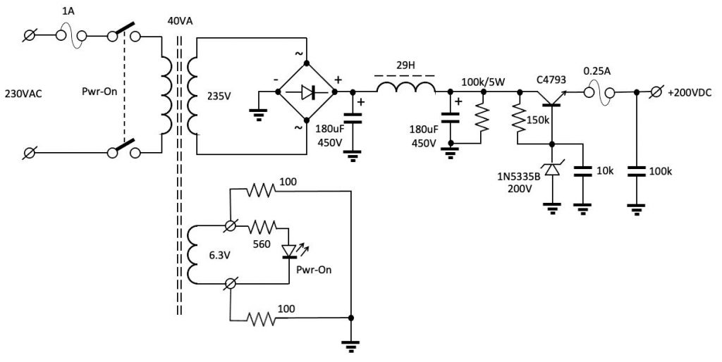
The power supply as seen in the above schematics is extremely simple. Yet, I ended up with a much more complicated circuit. Why? First of all, the transformer supplied a higher voltage then I needed. To bring it down I decided to use a voltage stabilizer circuit. I also used symmetrisation for the filament voltage, because the audio amplifier picked up lot of 50Hz hum. It did not completely disappear but brought it down to a bearable minimum.
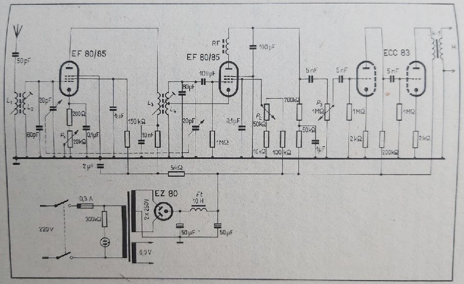
The rest of the circuits are:
- a radio-frequency amplifier with EF80 and with two tank circuits for providing band-pass filtering on the 80m-band. This required a two-gang variable capacitor and a vernier drive to fine tune it. This gave me a lot of mechanical issues to deal with. I used two T94-2 toroids for the tank circuits. Being relatively close to each other they are prone not to couple the RF and oscillate.
- the audion or rather regeneration circuit with EF80, is based on the principle of a Hartley oscillator. Controlling its second grid voltage, the oscillation can be stopped and adjusted to a critical level so that it will only oscillate when a signal triggers it. This basically re-generates the signal of a transmitting morse code by oscillating when transmission is present.
- the audio amplifier circuit with ECC83. There is nothing special about it, but it easily picks up the 50Hz hum, so be careful. For example, the filament supply could be provided through a rectifier circuit but be cautious these tubes require 6.3V DC or AC either way. The balancing of the filament voltage to ground helps, but not enough at high amplification.
What were my findings? First, let me provide the most important conclusions or rather warnings: - Be extremely careful, because tube circuits usually need high voltages. In my case there is a 360V DC after the rectifier, then stabilized to 200V. Both may cause fatal accidents. I have touched the switched off power supply and got hit, luckily between two of my fingers. The bleeding resistor has not yet discharged the capacitors. I realized that it takes more than about 10-seconds before they are sufficiently discharged, at least in this design. Later I waited about 10-seconds and then to be sure I shorted the capacitors before touching anything.
- However, sometimes it is inevitable that you touch the radio, for example tuning a tank circuit. Well, be extremely cautious and use your right hand only, and only touch it with a plastic tool. Never touch the powered-on radio with both hands. Do not ever give it a chance that high voltage is conducted between your two arms. Remember, your heart is in between. And when you have higher voltages than what we are talking about here, such as 1,000V for a linear amplifier, find other ways to tune circuits without the power being on. With such voltages a mistake may be the last mistake you make.
- Unless you explicitly want to build something with electronics tubes for retro feeling only, pick something much simpler than a three-tube radio. Yes, there are simpler regenerative receivers than this. Remember the cost to build something with tubes is much more expensive than building with semiconductors.
- Not having a display showing the frequency is quite annoying. I used a signal generator to tune the tank circuits, but the vernier drive numbering scheme did not show me where I am on the band. This is because the large variable capacitor in series with a small capacitor provided a nonlinear tuning range.
- Surprisingly the selectivity is quite reasonable. Not as good as a modern receiver of course.
- Pentodes, like the EF80 may not be ideal for the Regen receiver, because they generate some noise. Triodes generate less noise, but they have less amplifications too. If I were to build another one, I would experiment with triodes.
- One does not need to worry about picking up the same transmission on the band as with the Direct Conversion (DC) receiver. Because in DC receivers the local oscillator is mixed with the incoming RF signal, there are two products generated by the mixer. So, there is no offset to worry about either with the regenerative receiver when tuning the transmitter to match that of the received station frequency. The disadvantage is that there is no local oscillator that you may use for the transmitter.
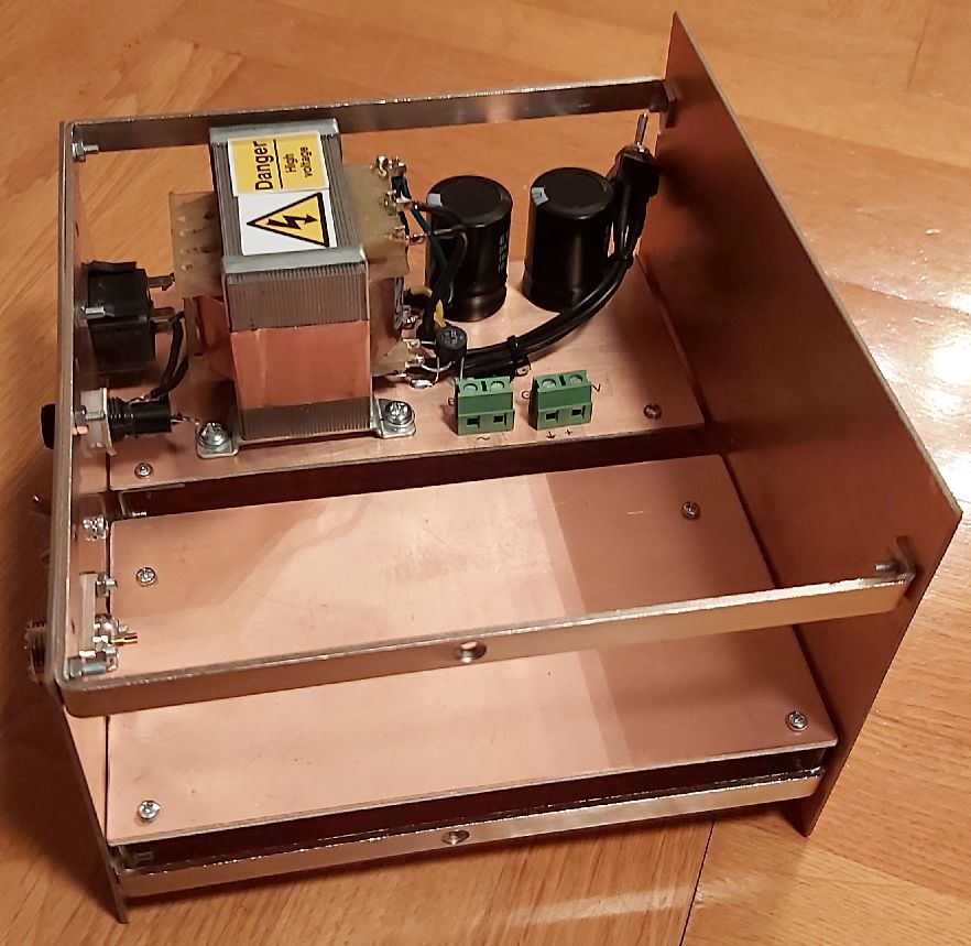
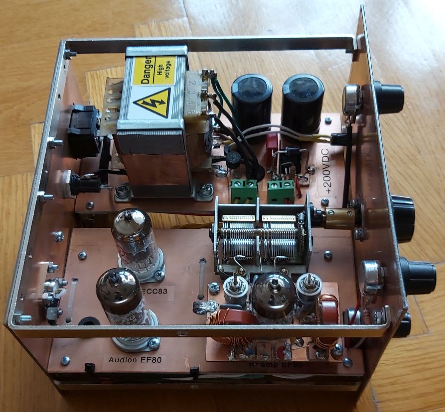
So, let’s see some pictures of various stages during the construction. This picture shows the partially built chassis with power supply.
This is the back panel:
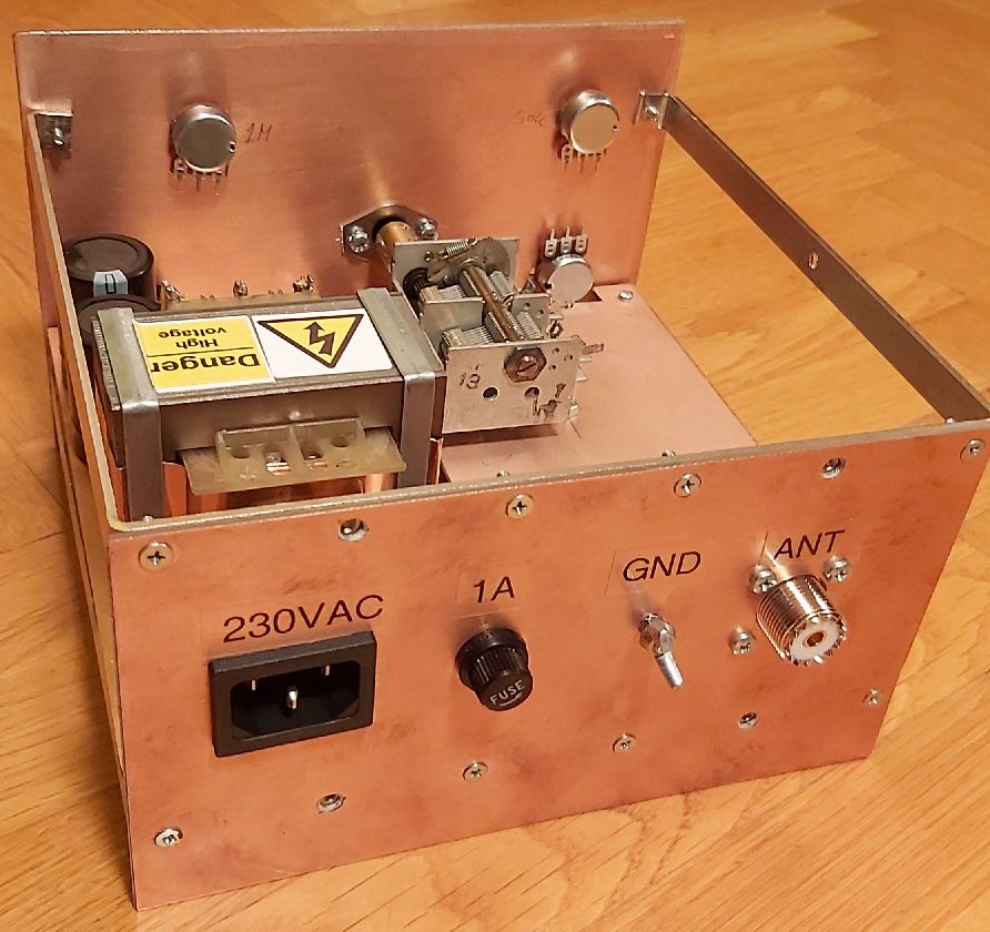
and this is the front panel:
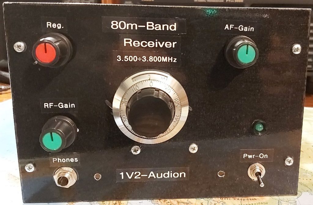
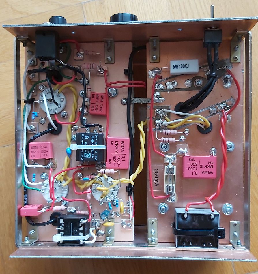
These are the completed project’s top and bottom views:
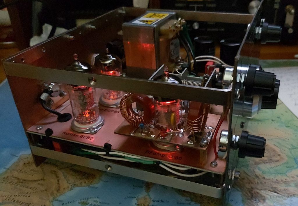
And finally, the glowing tubes in a dark room.
Oh, I almost forgot. After tuning the front-end tank circuits, I plugged in an antenna. Fiddling a bit with the potentiometers and tolerating some wild and loud high-pitched squeaks in my ear, suddenly a familiar 80m-band sound appeared. I heard morse code all over, it was some kind of a weekend contest. I tuned across the band and picked up a few CQs with their call signs and the typical UR 599s. The selectivity was fine, not comparable to my rig, but good enough to listen to a single station distinctively.
Normally, I use an FTdx3000 at my home QTH. Admittedly, I am not going to swap it for this newly minted tube receiver, not even if I build a matching transmitter to it. It was a nice project though, and I will make a few QSOs with it for sure when I build a transmitter as well. I will continue this article after I build the transmitter, so please stay tuned.
Ultimately, it will be a nice set of decoration on my shelf. I am sure my wife will refer to it by some other expression.
73!
István
HA5CLF / N9EU
Good morning. This is very good work. Congratulation.
Sincerely with my 73QRO F5NDL Jean-Pierre
Bonjour. Voilà du très bon travail. Félicitations.
Cordialement avec mes 73QRO F5NDL Jean-Pierre
Jo napot Istvan elnezest kerek a zavarasert kerlek segits nekem , kezdo vagyok es meg akarnam epiteni ezt a radiot de a kozep hullamra ! Tehat az L1,L2, L3, L4 es RF na meg a R3 alatti ellenalas ( K = ?? ) lenne a problemam. Elore is koszonom es minden jot kivanok tisztelettel Feri – Aradrol.
Interesting project; I have a few questions: what are the data of the L1/L2 and L3/L4 coils; what is the inductance of the RF choke; what transformer did you use at the ECC83 output. Without this data it will be difficult for me to make the same receiver. 73! Marian
Now in English: Interesting project; I have a few questions: what are the data of the L1/L2 and L3/L4 coils; what is the inductance of the RF choke; what transformer did you use at the ECC83 output. Without this data it will be difficult for me to make the same receiver. 73! Marian